This article supports procurement and project planning. It does not establish universal compatibility or a standard WAFU glass-door smart-lock SKU.
A glass door is only one part of a smart-lock closing system. The door configuration, hardware, mounting interfaces, closing behavior, power route and emergency-access responsibility all affect whether a proposed solution can enter sample validation.
1. Set the decision boundary before selecting a model
The first decision is not which lock model to order. It is whether the project has a documented interface that can be assessed. A statement such as “glass door” does not identify the parts that carry load, the available mounting surfaces, the closing direction, or the latch or strike relationship. Nor does it identify the responsible party for electrical and emergency-access work.
Treat a proposed lock as a candidate platform until the project team has reviewed the door and hardware information. A candidate may include WF-010, WF-019 or WF-026 when the intended use, installation envelope and required access method justify a closer review. That does not establish compatibility by itself. The final decision should follow the relevant drawings, project hardware, sample installation and agreed acceptance criteria.
The assessment boundary should make clear who is responsible for each interface: the door and glass-hardware supplier, the installer, the access-control or lock supplier, the electrical contractor, and the project operator. When one of those interfaces remains undefined, a quotation can still be prepared, but it should be conditional on the missing information and a sample review.
2. Record the door configuration, not just the material
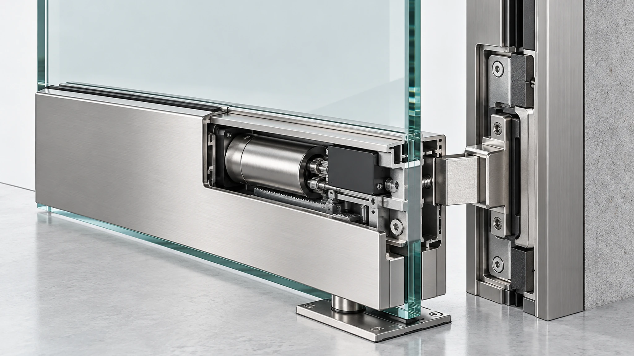
Before discussing a mounting method, record the actual door configuration. The key distinction is usually not glass versus non-glass; it is how the moving leaf closes and what stable structure exists on the strike side.
For example, a frameless single leaf may use patch hardware and close against a fixed glass panel, wall-mounted keeper or separate frame condition. A framed glass leaf may offer different mounting and cable-routing possibilities, but the frame material, section geometry and hardware still need review. Double-leaf arrangements introduce a meeting-stile or inactive-leaf condition that can change the available strike interface. Pivot, swing, sliding and special fire-rated or controlled-door systems require their own project constraints and should not be treated as interchangeable.
Collect at least front, rear and edge photographs; a door and hardware drawing where available; the opening direction; clear photographs of the closing side; and the current closing or latching hardware. Record whether the project expects remote release, credential access, local control or a defined combination. This package gives a supplier something concrete to assess and avoids designing around an assumed door condition.
3. Assess the mounting and strike interface as one system
A lock body, its mounting bracket or clamp, the moving leaf, the keeper or strike, and the fixed support must be assessed as one mechanical relationship. Looking at only the lock body leaves the most important question unanswered: where does the closing force go, and what maintains the required relationship after repeated use?
The review should identify the structural mounting surfaces, the available space around handles and patch fittings, the strike-side support, cable and battery-service access, and whether existing door hardware can remain in service. It should also identify any drilling, clamping or adapter work proposed for the glass or adjacent structure. Such work must be reviewed against the project hardware and glass supplier requirements; it should never be assumed from a generic article.
Where a product platform appears promising, ask for an installation concept that shows the proposed bracket, body and keeper positions against the actual door geometry. The concept should be checked before a production order and then reproduced on the sample. It is useful for a drawing to distinguish confirmed dimensions from items still pending measurement, rather than presenting generic dimensions as if they were confirmed.
4. Define power and emergency access before installation
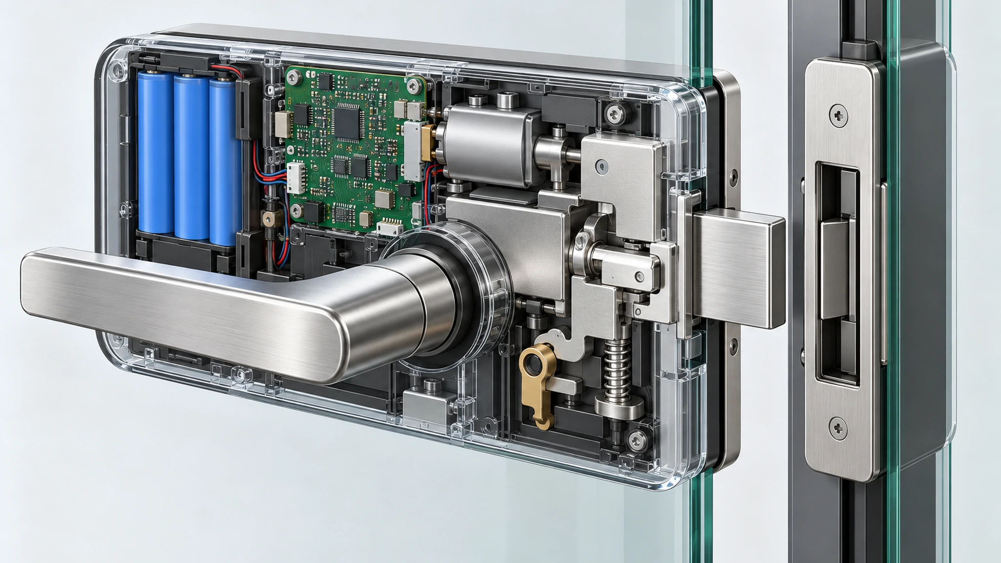
Power and emergency access are operational design decisions, not end-of-installation details. The project needs to define who monitors the power condition, who can replace or service the energy source, what happens when normal operation is unavailable, and which personnel are authorized to use an emergency path.
Start with the proposed access method and operating responsibilities. Each of these options—battery-powered, wired supply, controlled release or mixed—has different installation and maintenance dependencies. The assessment should locate any power interface, service access, cable transition and enclosure opening method without claiming a specific battery life or electrical performance until the final configuration has been tested.
Emergency access also needs a written project rule. The right path depends on the building, use case, local requirements and retained door hardware. It may involve a mechanical procedure, an authorized power or release method, a managed credential, or a site-specific response procedure. The sample review should demonstrate the agreed path with the responsible project parties present. Do not describe an untested illustration as a guaranteed emergency-opening solution.
5. Validate alignment through the full closing cycle
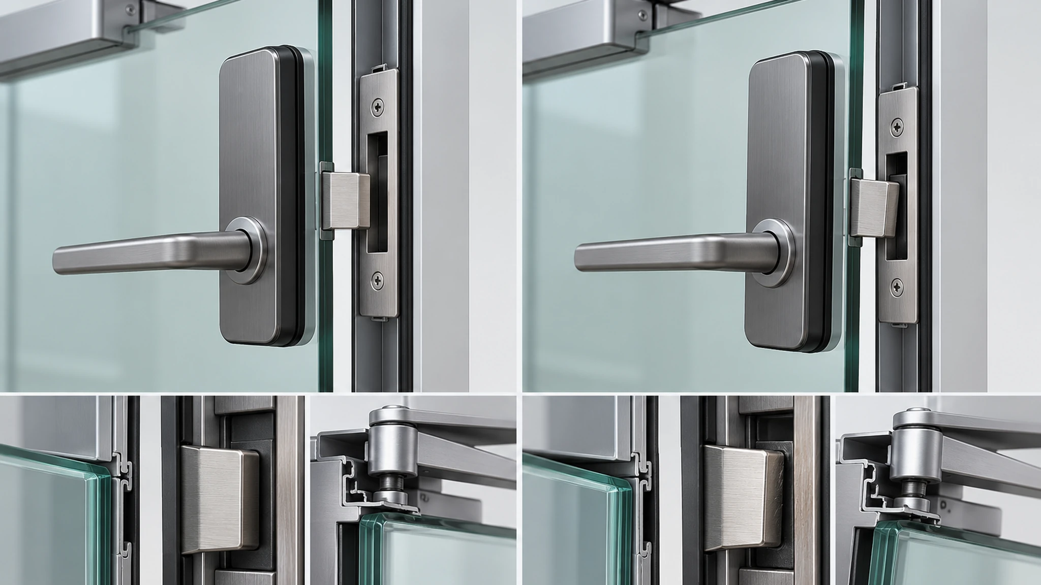
Static alignment at the fully closed position is not enough. The sample must be observed through the full cycle: approach, initial contact, final closing, lock engagement, release and reopening. Door sag, closer force, seal resistance, handle use, floor condition and hardware adjustment can change the relationship between the lock-side part and keeper over the cycle.
The project team should agree on the observations that matter for its installation: does the leaf reach its intended closed position consistently; does the keeper relationship remain stable; is there rubbing, impact or binding; can the normal access method operate after repeated cycles; and does the installation remain secure and serviceable? These are observations to record on the actual sample, not universal performance claims.
Where the door is used heavily or where closing conditions vary, repeat the validation after the hardware is adjusted to its intended project condition. If alignment depends on temporary shims, hand pressure or an installer holding the leaf in place, the interface has not yet been validated.
6. Use a sample test to turn assumptions into observations
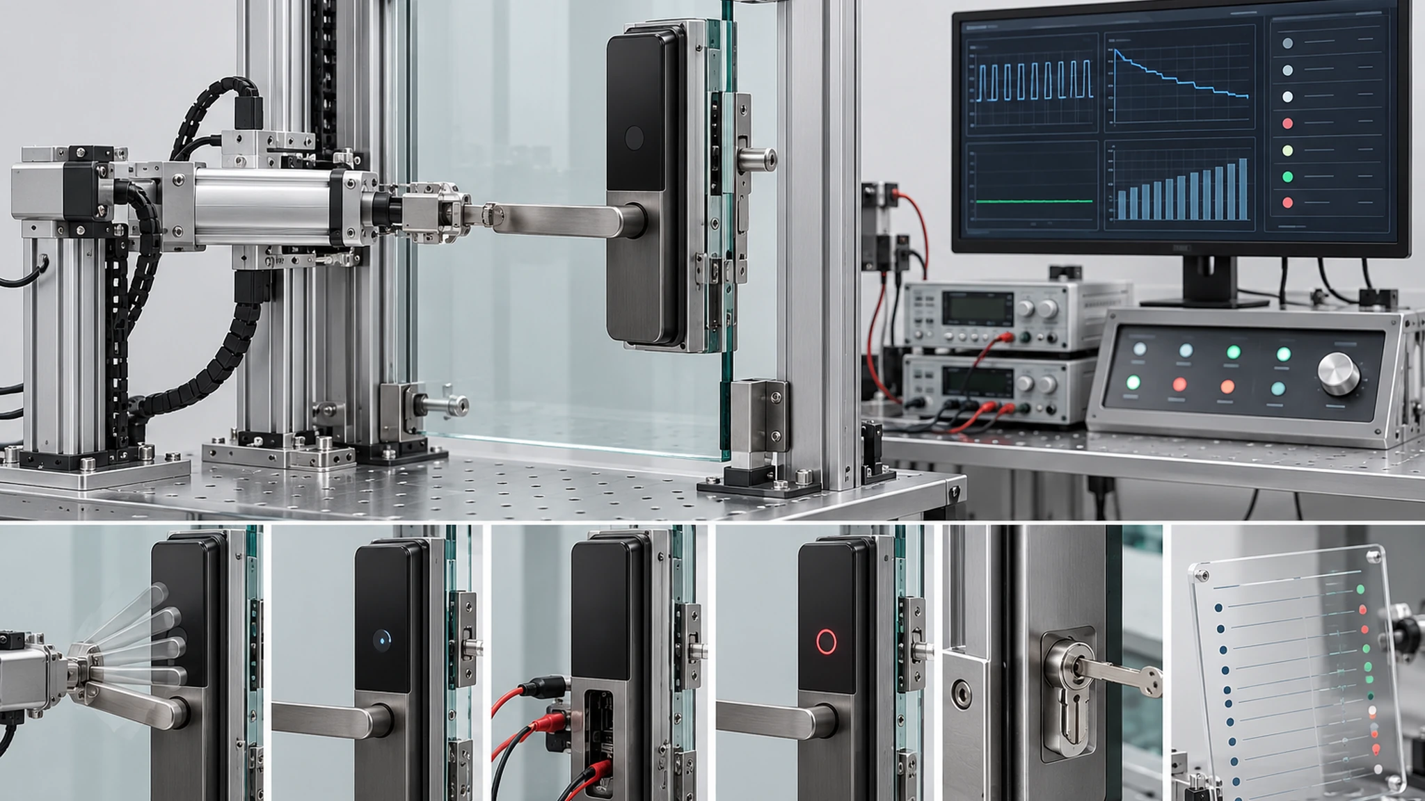
A sample test is the point at which the project replaces assumptions with evidence. It should include the intended door configuration or a mock-up that can be shown to be equivalent, the proposed mounting interface, the selected access method and the agreed service or emergency-access arrangement. A single successful unlock does not validate the project.
Use a simple record that identifies the sample components, configuration date, door condition, participants, observations and open actions.
| Validation topic | What the project team should observe |
|---|---|
| Door and hardware fit | Mounting surfaces, clearance around hardware, strike-side support, service access and any proposed adapter or clamp |
| Closing and engagement | Repeatable closing, keeper relationship, absence of unacceptable rubbing or binding, and stable engagement under the agreed door condition |
| Normal access | The project-selected access method, authorization behavior and user-facing operating sequence |
| Power and service | Access for planned maintenance, low-power handling procedure and responsibility for routine checks |
| Emergency access | The agreed authorized procedure, responsible personnel and conditions under which it may be used |
| Handover control | Component list, configuration record, installation notes, unresolved risks and approval responsibility |
The sample report should not convert observations into unsupported guarantees. It should record what was tested, under what configuration, what passed, what requires modification and what must be reconfirmed before production or site rollout.
7. Prepare a reviewable RFQ package
An RFQ is easier to evaluate when it separates known project facts from open questions. Attach the door information and state what the lock is expected to do. Do not ask a supplier to infer the full installation from one broad photograph or a model name.
- Door configuration, opening direction, door and hardware drawings if available, plus clear front, rear, edge and closing-side photographs.
- The proposed project location and use case, including whether local code, building management or specialist-door requirements may apply.
- Expected access methods and any access-control, credential, remote-release or operator-management requirements.
- The available fixed-side structure for a keeper, strike or interface bracket, and any limits on drilling, clamping or modification.
- Power expectations, maintenance responsibility and the project’s required emergency-access procedure.
- Quantity, sample schedule, target market, packaging or labeling needs, and the party responsible for final installation approval.
- Any required documents, inspection records, change-control process or handover materials.
This does not remove the need for a sample. It gives the project and supplier a shared basis for defining the sample scope.
8. Conclusion
Glass-door smart-lock work should begin with the closing system, not a catalog selection. A viable project needs a documented door configuration, a confirmed mounting and strike interface, a defined power and emergency-access responsibility, and a sample that demonstrates the intended closing and access behavior.
WF-010, WF-019 and WF-026 can be discussed as candidate platforms only after the drawings, hardware and project requirements are available. For an initial assessment, submit the door information, intended access method and project operating requirements. The next useful step is normally a drawing review followed by a sample installation and recorded validation, rather than any claim of universal compatibility.
Request a glass-door project assessment
Send the door drawings or photographs, opening direction, hardware condition, target quantity, access requirements, power expectations and planned emergency-access procedure. WAFU can use this information to define drawing review and sample validation requirements.
This article supports procurement and project planning. It does not establish universal compatibility or a standard WAFU glass-door smart-lock SKU.