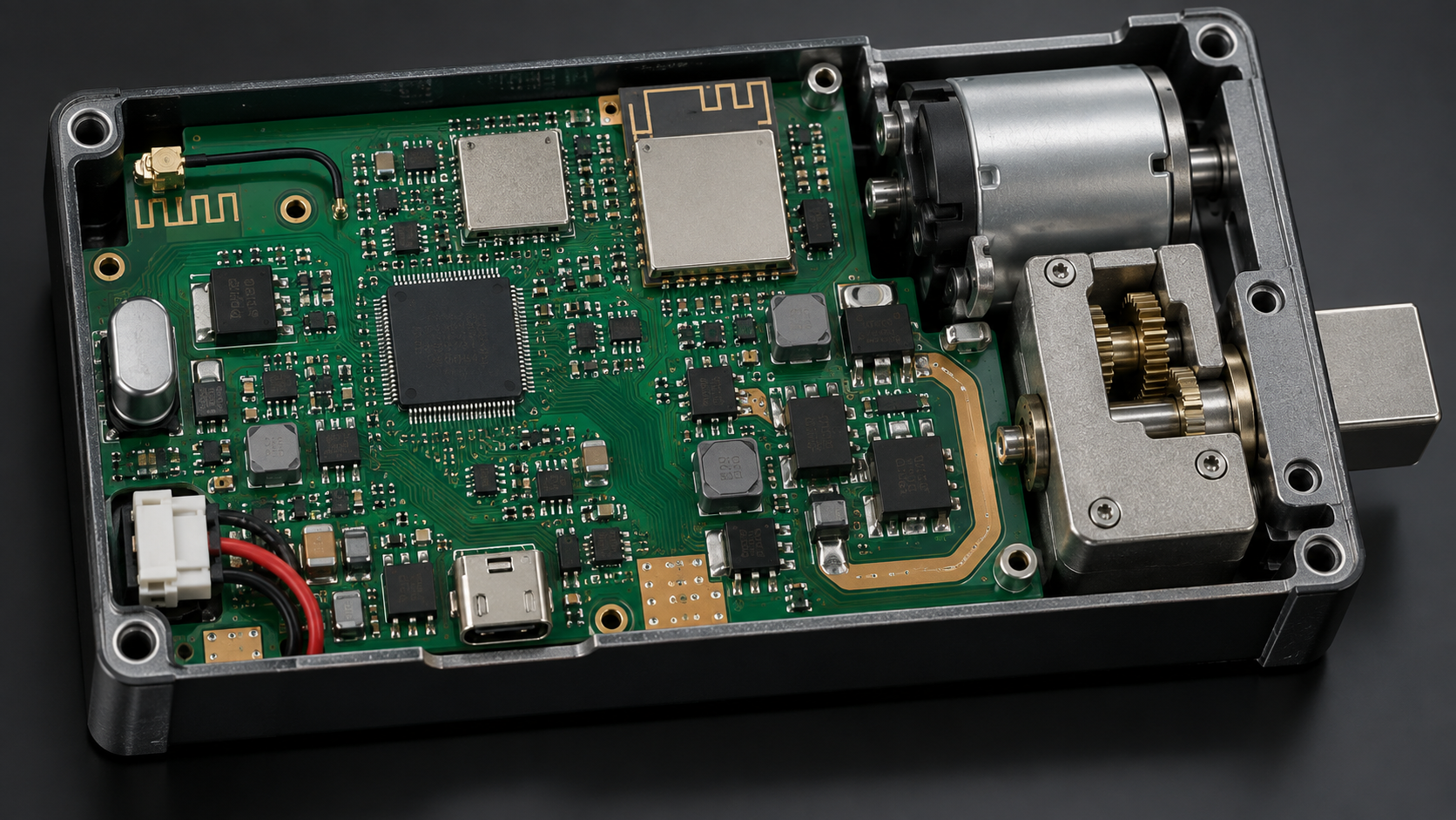
This article explains engineering principles. It does not publish a guaranteed range for any WAFU product or cabinet configuration; range and reliability must be verified on the final enclosure.
A wireless lock can work perfectly on an open bench and lose range as soon as the metal cabinet closes. The enclosure becomes part of the RF system: it reflects energy, detunes the antenna, blocks some propagation paths and couples motor noise into the radio. Reliable design therefore starts with PCB placement and ends with a closed-door test on the real cabinet.
1. Treat the metal enclosure as an RF boundary
Steel and aluminum surfaces reflect and absorb radio energy. A mostly closed cabinet can behave like a partial Faraday enclosure, leaving door gaps, hinges, cable openings and non-metal windows as the main leakage paths. Small geometry changes may produce a large difference in link quality.
The lock position, antenna orientation and user position must be evaluated together. An antenna facing the cabinet interior may couple into the enclosure instead of the intended receiver outside.
2. Compare 433 MHz, Bluetooth and Wi-Fi by project role
433 MHz can support simple low-power remote control and may tolerate some obstruction, but antenna size and regional radio requirements still matter. Bluetooth is convenient for nearby phone access and commissioning. Wi-Fi supports network connectivity but usually requires more energy and depends on access-point placement.
Frequency alone does not guarantee penetration through metal. Protocol overhead, antenna efficiency, output power, receiver sensitivity, duty cycle and enclosure geometry all contribute to the usable link budget.

3. Protect antenna keepout and placement
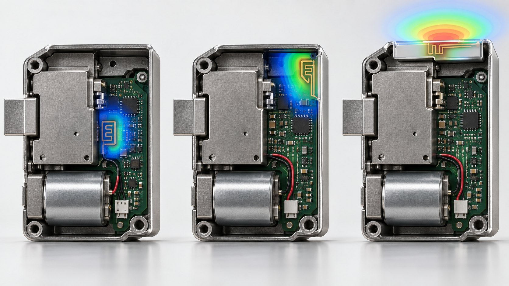
Keep copper, ground, batteries, motors and metal brackets away from the antenna region according to the selected module or antenna design. Positioning the antenna at a cabinet edge or behind a controlled non-metal window can be more effective than increasing transmit power.
Evaluate the assembled product, not only the bare PCB. Wiring, screws, shielding cans and a changed battery holder can detune an antenna that looked acceptable during board-level testing.
4. Separate motor noise from the radio path
The motor creates current steps, brush noise and supply droop during locking. Use an appropriate power path, local decoupling, grounding strategy and routing separation so the radio and controller remain stable at the worst mechanical load.
Test communication while the motor starts, stalls briefly and reverses. A design that communicates only when the actuator is idle may fail at the exact moment a remote unlock command must be confirmed.
5. Validate with the cabinet closed
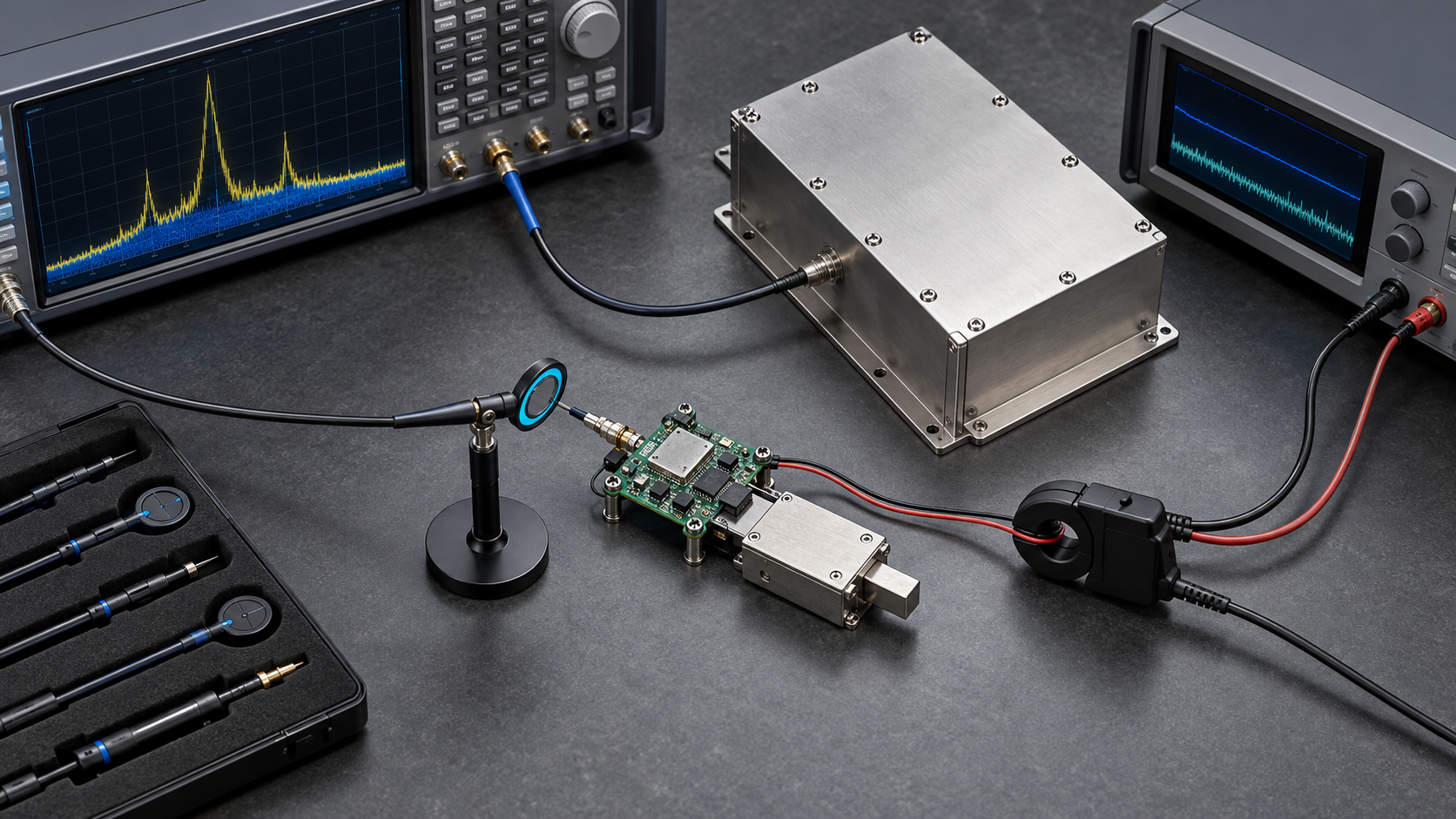
Measure pairing, command success, response time and recovery with the cabinet open and closed, at intended user positions and with nearby cabinets populated. Include low battery, repeated operation and the actual gateway or access point.
Record test orientation, distance, cabinet material, door gap, antenna version, firmware and power condition. A single maximum-range number without these conditions is not a useful acceptance criterion.
6. Choose an architecture from evidence
If the antenna cannot be placed near an RF-transparent boundary, consider a protected external antenna, a wired reader, an external gateway or a different authorization architecture. The right answer may be a mechanical and electrical redesign rather than a radio setting.
Freeze antenna geometry, enclosure material and cable routing with the approved sample. Production changes around the antenna require regression testing even when the schematic is unchanged.
7. Conclusion: the cabinet is part of the antenna system
For a metal-cabinet lock, RF design is not an isolated PCB task. Enclosure geometry, antenna keepout, grounding, motor current and the real installation jointly determine performance.
Define the cabinet and user path first, select 433 MHz, Bluetooth or Wi-Fi for a clear project role, then validate the complete closed assembly before volume release.
Project inquiry & OEM/ODM
Share cabinet drawings, panel material, quantities and wireless requirements so the project can define a defensible sample path.